In order to define the space of finite elements a triangulation of
the computational domain ![]() is needed. In the practical implementation
the triangulation is provided from an external file (triangulation file).
Program
FEMFLUID can use two input formats. Recently,
FEMFLUID uses mesh format
defined by the automatic anisotropic mesh generator ANGENER (V.Dolejsi, MFF
UK, Praha). The format of the input file then reads (in
FEMFLUID the second line is
ignored - in ANGENER used for periodical boundary)
is needed. In the practical implementation
the triangulation is provided from an external file (triangulation file).
Program
FEMFLUID can use two input formats. Recently,
FEMFLUID uses mesh format
defined by the automatic anisotropic mesh generator ANGENER (V.Dolejsi, MFF
UK, Praha). The format of the input file then reads (in
FEMFLUID the second line is
ignored - in ANGENER used for periodical boundary)

|
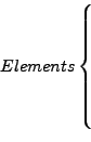
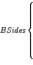
#Points #Elements #BoundarySides #Marks 0.0 0.0 0 0 0.0 0.0 0 0 PointX(1) PointY(1) PointX(2) PointY(2) . . . . . . PointX(#Points) PointY(#Points) ElementI(1) ElementJ(1) ElementK(1) ElementI(2) ElementJ(2) ElementK(2) ElementI(3) ElementJ(3) ElementK(3) . . . . . . ElementI(#Elements) ElementJ(#Elements) ElementK(#Elements) BndrSideI(1) BndrSideJ(1) BndrMARK(1) BndrSideI(2) BndrSideJ(2) BndrMARK(2) BndrSideI(3) BndrSideJ(3) BndrMARK(3) . . . . . . BndrSideI(#BSides) BndrSideJ(#BSides) BndrMARK(#BSides) |
The orientation of triangles needs to be chosen in the standard way. The orientation of boundary sides needs to preserve the orientation of the adjacent triangle, i.e. that the computational domain should be on the left hand side from the oriented boundary side.
Triangulation can be also read from files generated by the program TRIANGLE (optional, program changes needed).
The triangulation from Figure 1 is described with the following triangulation file
7 6 6 4
0.0 0.0 0 0 0.0 0.0 0 0
0.0 0.0
1.0 1.0
1.0 0.0
0.0 0.5
0.5 0.5
0.0 1.0
0.5 1.0
1 3 5
3 2 5
5 2 7
1 5 4
4 5 6
5 7 6
1 3 10
3 2 20
2 7 60
7 6 60
6 4 1
4 1 1
![\includegraphics[width=0.4\textwidth]{triangulation.eps}](img7.png)